CALL 800-985-6929
Mon-Fri 7AM - 7PM CST
Boston Gear 700 Series Double Reduction Worm Gear
Our standard 700 Series – the heart of Boston Gear’s speed reducer product line – has been serving industry reliably for over 40 years. Its proven modular design has set the industry standard for performance and is the most imitated product in today’s worm gear speed reducer market. But why settle for a knock-off when you can have the original – from Boston Gear.
CATALOG & MANUALS
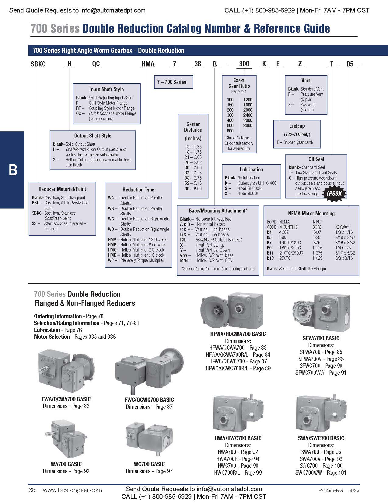
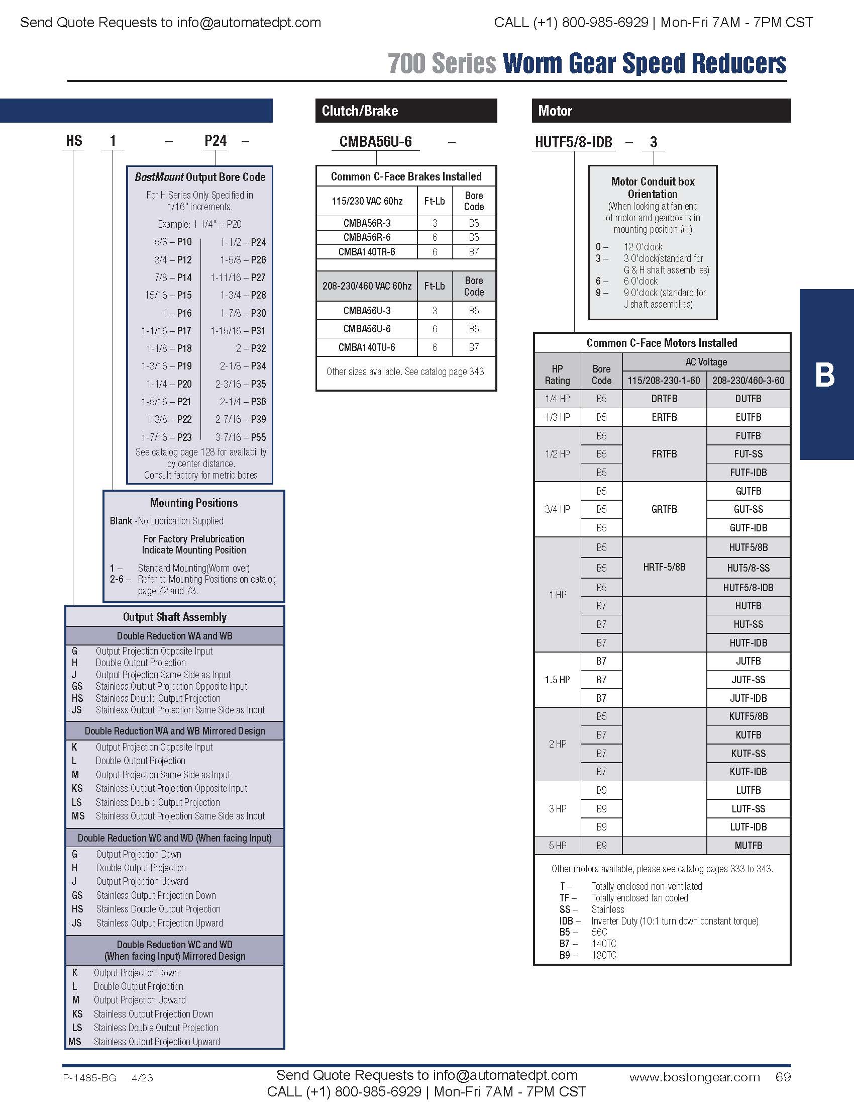
Double Reduction Numbering System / How to Order
When ordering reducers please include code letters for Style, Size,
Base (if required), Ratio, Lubrication (if required), NEMA Mounting (if
flanged reducer), Shaft Assembly and Motor (if required).
EXAMPLE:
Required size, 726 Quill types flanged double reduction reducer, 100 to 1 ratio, 5/8” input bore, parallel shafts, standard assembly, no base.
Motor to be 3/4 HP, 1750 RPM, 230/460 Volt, 3 Phase, 60 cycle, Open Dripproof.

Style
Style – Designates reducer or flanged reducer, projecting or hollow output shaft.
| C | Designates cast iron flange and base. (Standard on motor flanges 3 HP (180TC) and up and all bases except horizontal (710-726). |
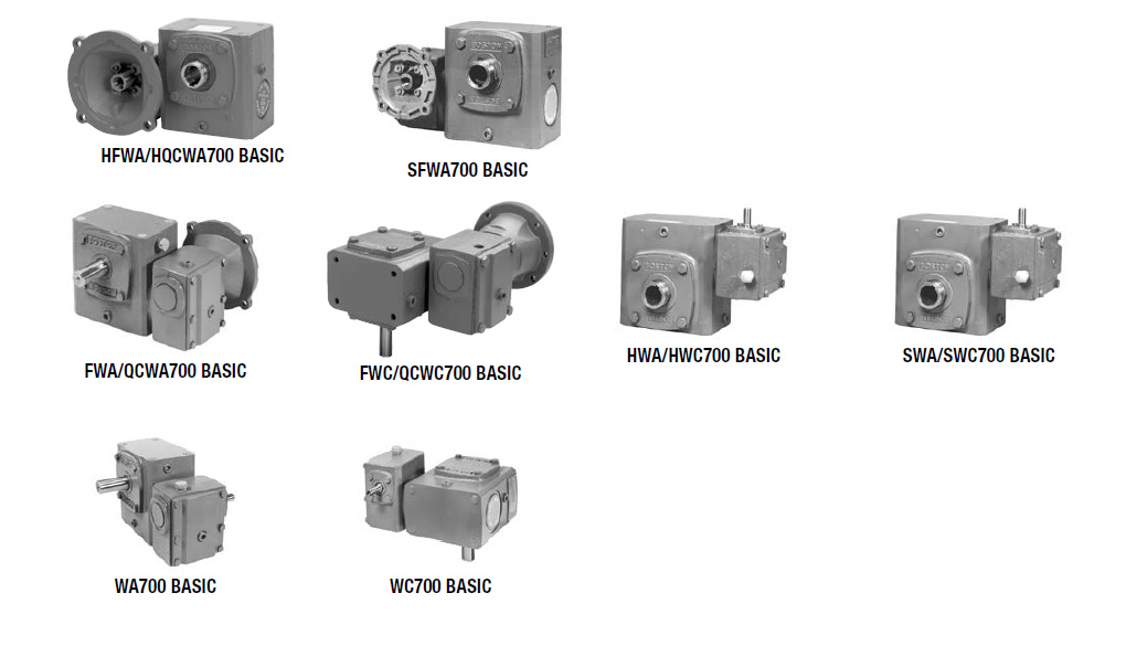
| WA | Double reduction, parallel shaft reducer with projecting output shaft. |
| HWA | Double reduction, parallel shaft reducer with BostMount hollow output shaft. |
| SWA | Double reduction, parallel shaft reducer with hollow output shaft. |
| WC | Double reduction, right angle shaft reducer with projecting output shaft. |
| HWC | Double reduction, right angle shaft reducer with BostMount hollow output shaft. |
| SWC | Double reduction, right angle shaft reducer with hollow output shaft. |
| FWA | Double reduction, parallel shaft flanged reducer (Quill types) with projecting output shaft. |
| HFWA | Double reduction, parallel shaft flanged reducer (Quill types) with BostMount hollow output shaft. |
| SFWA | Double reduction, parallel shaft flanged reducer (Quill types) with hollow output shaft. |
| FWC | Double reduction, right angle shaft flanged reducer (Quill types) with projecting output shaft. |
| HFWC | Double reduction, right angle shaft flanged reducer (Quill types) with BostMount hollow output shaft. |
| SFWC | Double reduction, right angle shaft flanged reducer (Quill types) with hollow output shaft. |
| QCWA | Double reduction, parallel shaft flanged reducer (Coupling types) with projecting output shaft. |
| HQCWA | Double reduction, parallel shaft flanged reducer (Coupling types) with BostMount hollow output shaft. |
| QCWC | Double reduction, right angle shaft flanged reducer (Coupling types) with projecting output shaft. |
| HQCWC | Double reduction, right angle shaft flanged reducer (Coupling types) with projecting output shaft. |
| SSFWB/SSFWD | Stainless steel double reduction with solid output shaft. |
| SSHFWB/SSHFWD | Stainless steel double reduction with hollow output shaft. |
Size
SIZE – Center distance, rounded off. On double reduction models this is the Center Distance of the second reduction.
713 – 1.33
718 – 1.75
721 – 2.06
726 – 2.62
730 – 3.00
732 – 3.25
738 – 3.75
752 – 5.16
760 – 6.00
Base
BASE – Base positions relative to output shaft. Shipped separately as Base Kits.
| Blank | No base kit |
| A,B | Horizontal bases |
| C,D,E & F | Vertical Bases |
| R/L | BostMount Output Bracket |
| X | Input Vertical Up |
| Y | Input Vertical Down |
| V,W | Flanged bases, available on “S” hollow shaft models only. Factory assembled. |
| M,N | Hollow Output with CFA |


Lubrication
Lubrication Optional Prelubrication.
Blank – No Lubrication supplied.
K – Klubersynth UH1 6-460
S – Mobil SHC 634
X – Mobil 600W
*When specifying optional prelubrication, include
mounting position after shaft assembly.
Vent
VENT – Pressure Relief.
Blank – Standard Vent
P – 5 PSI Vent
Z – PosiVent® Pressure Compensationg Bladder
When specifying optional prelubrication, include mounting
position after shaft assembly.
Seals
Input Oil Seals
Blank – Standard Seal
T – Double Input Seals. Recommended for mounting positions
2, 3, 4, 6
Nema Mount
Nema – Designates flange size and input bore diameter. Flanged reducers only. Leave blank for projecting input reducers.

Shaft Assembly
Shaft Assembly
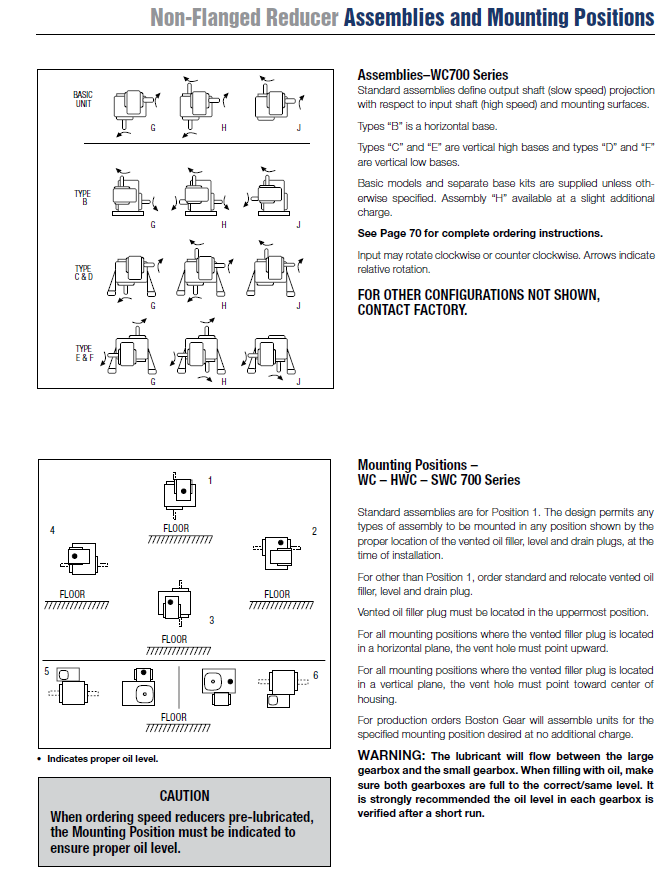
Assembly shaft arrangements.
G* – Standard assembly
H* – Double output shaft projection
J* – Opposite to standard
* Add “S” after letter for Stainless Steel Shaft (ex. GS, HS, JS)


Double Reduction Speed Reducer Selection Procedure
To properly select a speed reducer, the following application information must be known:
Input RPM (Ratio)
Output Torque
Input Horsepower
Service Factor
Non-Motorized Speed Reducer
1. Determine service factor from table below.
2. Determine design horsepower.
Design Horsepower = Application Load x Service Factor
3. Select a speed reducer size that satisfies output RPM, service class and/or output torque requirements.
4. Check overhung load capacity.
Motorized Speed Reducer
1. Determine service class from table below.
2. Select a reducer size that satisfies output RPM, service class and/or output torque requirements.
3. Check overhung load capacity.
Service Factor Table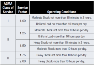
For complete AGMA Service Factors and Load Classifications,
see Engineering Section, Pages 349 and 350.
Double Reduction Selection Tables
Capacity selection tables on Pages 77-81 list catalog numbers
and ratios of both reducers and gearmotors. Output RPM,
output torque and horsepower are all based on 1750 RPM
input. For motorized reducer selection, select the desired
output RPM and refer to the gearmotor ratings column. For
non-motorized reducers, refer to the reducer gear capacity
columns. For the desired HP, torque and service factor that
satisfies your requirements, a 700 Series basic reducer
number will be indicated. For complete catalog part number,
descriptions and options, refer to Page 70.
Overhung Load
If the output shaft of a speed reducer is connected to the
driven machine by other than a flexible coupling, an overhung
load is imposed on the shaft. This load may be calculated as
follows:
OHL = 2TK
D
OHL = Overhung Load (LB.)
T = Shaft Torque (LB.IN.)
D = PD of Sprocket, Pinion or Pulley (IN.)
K = Load Connection Factor
Load Connection Factor
Sprocket or Timing Belt ……………………………………………… 1.00
Pinion and Gear Drive ……………………………………………….. 1.25
Pulley and V-Belt Drive ………………………………………………. 1.50
Pulley and Flat Belt Drive ……………………………………………. 2.50
An overhung load greater than permissible load value may be
reduced to an acceptable value by the use of a sprocket, pinion
or pulley or a larger PD. Relocation of the load closer to the
center of reducer will also increase OHL capacity.
Permissible overhung loads and output shaft thrust loads are
listed for each reducer in the tables on Pages 30-33.
Maximum Input Speeds
W713, W718, W721, W726 ……………………………………… 4500 RPM
W730 through W760 ……………………………………………….. 3600 RPM
NOTE : Horsepower ratings for 1750 RPM should NOT be
exceeded when operating at higher input speeds.
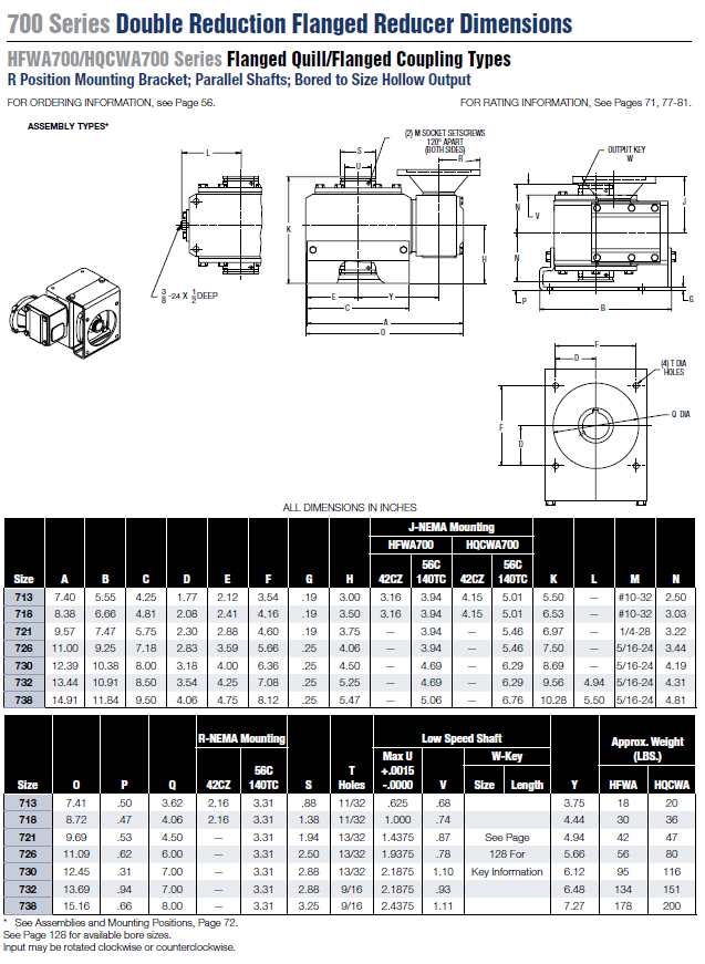
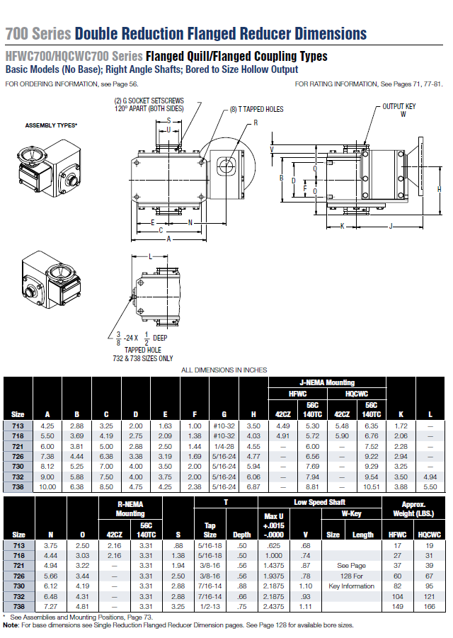
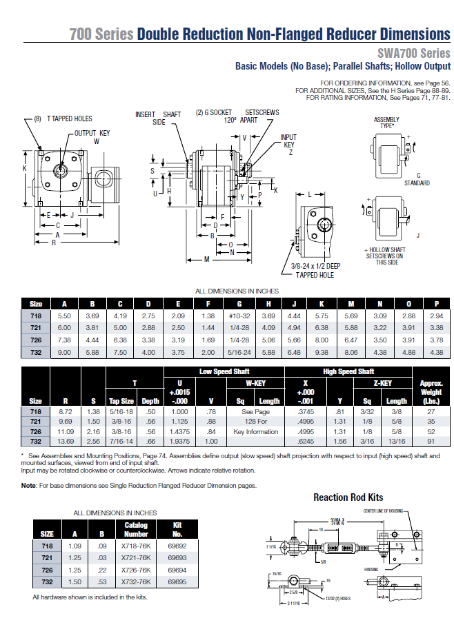
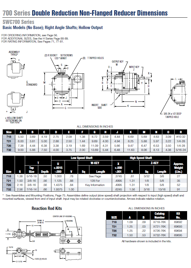
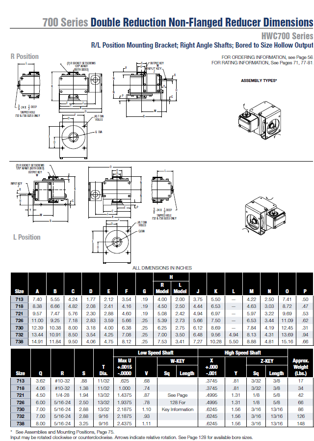
Dimensions